
Welcome to Ken Boone's Robotic Home Page
 I
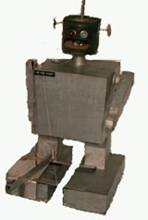
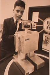
have been experimenting with amateur robotics for a long time. My first robot
was named Rob Robot and was constructed in 1963 for an elementary school
science fair. Rob looked like most of the science fiction robots of that time.
I improved Rob the next year and won the local science fair.
I
have been experimenting with amateur robotics for a long time. My first robot
was named Rob Robot and was constructed in 1963 for an elementary school
science fair. Rob looked like most of the science fiction robots of that time.
I improved Rob the next year and won the local science fair.
Rob Robot
 The
idea for building Rob came from a construction article in the March 1962 issue
of "Popular Electronics" on building Emily the robot. I improved
Rob’s sensitivity by adding a second transistor to his circuit in a darlington
pair arrangement. He could follow a
white line on the floor or follow a light beam. Rob won third place in the
state regional contest. I later learned that the judges thought my exhibit was
the best one but they did not believe I had done all the work. Well at least I
know it was the best.
The
idea for building Rob came from a construction article in the March 1962 issue
of "Popular Electronics" on building Emily the robot. I improved
Rob’s sensitivity by adding a second transistor to his circuit in a darlington
pair arrangement. He could follow a
white line on the floor or follow a light beam. Rob won third place in the
state regional contest. I later learned that the judges thought my exhibit was
the best one but they did not believe I had done all the work. Well at least I
know it was the best.
After the science fair Rob spent several years as a remote controlled high school basketball mascot. In 1987 Rob was modified to add a block catcher and a light detector. The catcher and light detector allowed him to compete in our next robotic club's annual contest. That year the robot had to find a white block in an eight by eight foot black robotic play pen and put the block in a six inch square hole under a light bulb. Rob was able to get one of the four blocks to the hole almost every time.
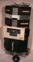
Jr. Robot
 The
next robot built was named Jr. by my wife. It started out as an early HEP
training kit with a Motorola 6800 microprocessor. First I modified it to drive
two stepper motors. At first it was just programmed to wonder around and avoid
objects using just a front bumper then a robotic hand and a remote control was
added.
The
next robot built was named Jr. by my wife. It started out as an early HEP
training kit with a Motorola 6800 microprocessor. First I modified it to drive
two stepper motors. At first it was just programmed to wonder around and avoid
objects using just a front bumper then a robotic hand and a remote control was
added.
 About
this time I read an excellent robotic article titled "A Mobile Cognitive
Robot" in the June 1977 issue of BYTE magazine. The article inspired me to
start working on an intelligent robot. (Look up the article. It is still
relevant)
About
this time I read an excellent robotic article titled "A Mobile Cognitive
Robot" in the June 1977 issue of BYTE magazine. The article inspired me to
start working on an intelligent robot. (Look up the article. It is still
relevant)
The 6800 computer was modified to have 2k of memory instead of 128 bytes and four parallel ports were added.
The goal of the new robot was to have all of its systems controlled by the computer with a remote control only giving the robot commands. The robot was finished in 1981 just before my daughter was born. It was a good thing that it was finished then because life as I knew it changed drastically.
 Jr.
has a hand that opens, closes, rotates and lifts from the floor to the top of
the robot. An attachment for the hand allows Jr. to launch paper airplanes. Another
attachment allows him to hold a felt tip pen. A pen holder was also built into
the center of the base of Jr. The pens are raised and lowered using the hand
lift controls.
Jr.
has a hand that opens, closes, rotates and lifts from the floor to the top of
the robot. An attachment for the hand allows Jr. to launch paper airplanes. Another
attachment allows him to hold a felt tip pen. A pen holder was also built into
the center of the base of Jr. The pens are raised and lowered using the hand
lift controls.
Locomotion is provided by two stepper motors. The stepper motors drive two large toothed gears with timing belts. The large gears are the wheels and the belts are the tires. Jr. moves forward, backwards or rotates either direction
His program has several modes of operation. In the first mode Jr. is operated using a remote radio link. All of his actions are controlled using a modified calculator that sends hexadecimal commands to the computer. The second mode is a numerical control mode where the hexadecimal commands are entered directly in memory and Jr. executes them in sequence when commanded by the remote to run a stored program. With one of the numerical control programs Jr. writes its name. There are looping commands and commands for how long or how far for the different actions. The last mode is a teach mode. In this mode Jr. remembers everything it does and saves the commands in the program storage area. Then Jr. can repeat the actions at the command of the remote control.
Jr. has logged a lot of time visiting local schools, launching paper airplanes at coworkers and making a mandatory appearance at each of my daughter’s birthday parties. (Until she entered middle school) He still works and makes an appearance at Duke University TIP every time I teach there. My Duke TIP classes are described later in my robotics history.
Then in January 1984 the local home brew computer club reorganized to become
a computer  experimenter and hobby
robotics club. They reorganized because at that time it became less expensive
to buy a computer then to build one your self.
I attended the organizational meeting with Jr. This group (now called) Triangle Amateur Robotics is
still active and still encourages me to continue working on my robotics projects.
Check out the club history on the club’s web site. Well, back to the lawnmower.
experimenter and hobby
robotics club. They reorganized because at that time it became less expensive
to buy a computer then to build one your self.
I attended the organizational meeting with Jr. This group (now called) Triangle Amateur Robotics is
still active and still encourages me to continue working on my robotics projects.
Check out the club history on the club’s web site. Well, back to the lawnmower.
Robotic Lawnmower Test Bed
In 1983 one of my coworkers (Roy Miller) challenged me to build a useful
robot that would mow grass. A task he hated to do. This intrigued me and again
I started on another robot. For the first year all I did was talk with Roy
about the robot during lunch. We discussed how to do the mowing, locomotion,
navigation etc. 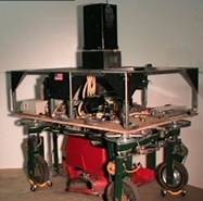
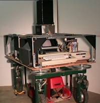
The lawnmower was a very big project. It is presently in its third platform. The first one was a three wheeled unit with three wheel drive. That platform was unstable and flipped over too easy. The second had four wheel drive with four wheel steering. It had traction problems. Even though it had four wheel drive, uneven ground would lift two of the wheels off of the ground. The third platform (I call it the “Robotic Lawnmower Test Bed”) has four wheel drive and four wheel steering with the front two wheels attached to a bar on the front of the chassis that pivots to keep all four wheels on the ground like the front wheels on some riding mowers.
 The
robot moves forward and backwards with its wheels pointing straight ahead. When
it turns it stops and uses a single motor to turn all the wheels tangent to the
center of the robot. Then the robot can rotate in place without changing
location. I
The
robot moves forward and backwards with its wheels pointing straight ahead. When
it turns it stops and uses a single motor to turn all the wheels tangent to the
center of the robot. Then the robot can rotate in place without changing
location. I 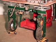 designed
the steering this way to simplify navigation.
designed
the steering this way to simplify navigation.
I found a Toro 12 volt electric push lawnmower deck and incorporated it into the third platform. The deck saved a lot of time designing something to cut the grass. Work on this project was very slow. Typically I would work on it a couple of months each year just before the annual club contest. That is unless I was working on a robot to enter in the contest.
At present the lawnmower is controlled by a Radio Shack Color Computer. An
interface was built to drive the four drive motors and the steering motor. One
of the drive motors has an encoder to determine how far the robot turns or 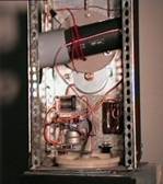 moves.
I designed/built an inverter to provide 120 volt ac to the computer and its
disk drive.
moves.
I designed/built an inverter to provide 120 volt ac to the computer and its
disk drive.
Most of the work up to this point went fairly fast. Two to three years. Then there was the problem of navigation. I was determined to make the robot self guiding. That meant that the robot has to know where it is and be able to plan the route to take to mow the grass. After several years of experimenting with lasers and beacons a transit was designed for the robot in 1992. The transit turns around and locates infrared beacons that have emitters on the top and bottom of tall poles. The emitters on each pole send out a 40kH signal. Each pole identifies itself by modulating the 40kH signal on and off at different frequencies. The computer turns the transit until it sees the top of one of the beacons to determine its direction from the robot then the computer turns the detector down until it sees the emitters on the bottom of the beacon using the angle moved to calculate the distance to the beacon. The present transit is not accurate enough to do the navigation for mowing.
In the future an RF modem is planned and possibly a complete redesign of the chassis (It is too big.). All of the navigation problems could be solved with a differential GPS system but that is too expensive. The on board computer needs to be upgraded. The 64k Color Computer does not have the trig functions or the accuracy needed for the navigation calculations. Or the navigation and route planning could be done by a remote computer and commands transmitted to the mower. This mower project was never planned to be a product. Just a challenge and learning experience. Then there are the club contests to build robots for.
TAR Vision Contest
 In
1987 the Robotics Club (TAR) decided to do a club contest and I came up with
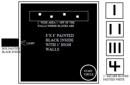
the Vision Contest. The contest arena was
eight foot square with one foot high walls and everything painted flat black
inside. Four numbered white blocks were
placed in a one foot wide area that was one foot from the walls opposite the
start circle. The blocks were randomly
placed in the block area with the numbered side up and had to be at least one
foot apart. The robot was placed by the
contestant in the start circle. The
first level of the competition was based on how long it took to get one block
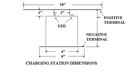
through a four inch square opening in one of the walls. The bottom of the opening was the floor,
there was a bright white light just above the opening and a box painted flat
black inside behind the opening to prevent light from coming out of the
opening. The second level included
putting all four blocks through the opening in the least time and the final
level included putting all four blocks through the opening in numerical order
in the least time. Notice that the
blocks are numbered such a reflective sensor in each corner of the block and
one in the center could determine the blocks number. The contest ran for several years and only
the first two levels were reached. I
think that this is still a good club contest to run now.
In
1987 the Robotics Club (TAR) decided to do a club contest and I came up with
the Vision Contest. The contest arena was
eight foot square with one foot high walls and everything painted flat black
inside. Four numbered white blocks were
placed in a one foot wide area that was one foot from the walls opposite the
start circle. The blocks were randomly
placed in the block area with the numbered side up and had to be at least one
foot apart. The robot was placed by the
contestant in the start circle. The
first level of the competition was based on how long it took to get one block
through a four inch square opening in one of the walls. The bottom of the opening was the floor,
there was a bright white light just above the opening and a box painted flat
black inside behind the opening to prevent light from coming out of the
opening. The second level included
putting all four blocks through the opening in the least time and the final
level included putting all four blocks through the opening in numerical order
in the least time. Notice that the
blocks are numbered such a reflective sensor in each corner of the block and
one in the center could determine the blocks number. The contest ran for several years and only
the first two levels were reached. I
think that this is still a good club contest to run now.
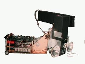
Video Robot
![]()
![]()
![]()
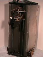
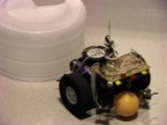
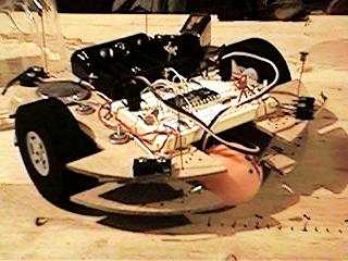
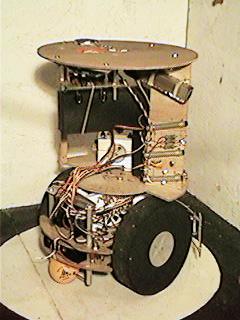
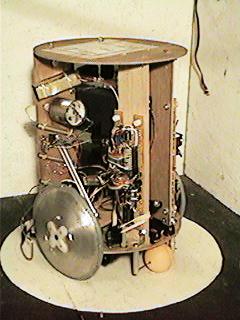
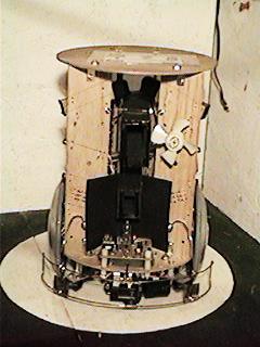
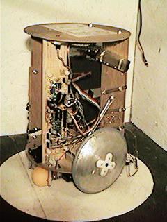
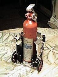
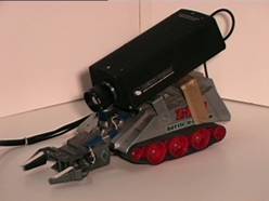 In
1987 I built a tele-operated robot to evaluate using a video camera to
In
1987 I built a tele-operated robot to evaluate using a video camera to ![]() locate
the blocks in the club vision contest. A Radio Shack “Iron Claw” remote control
toy was gutted and hard wired to a remote control panel. An old surveillance
camera was attached to the top of the robot. The robot was operated remotely
while the operator looks at a video monitor. It is quite educational to operate
the robot seeing what the robot sees and try to locate blocks, pick them up and
put then in a small opening. I determined that it took too much computing power
(in 1987) to use the video camera to find the blocks, navigate and determine
the block number. However, the robot has seen a lot of action with people
operating it at various club functions. For the years we ran the vision contest
we let visitors compete against each other using the robot to perform the
contest. This robot has outfitted with a new lighter video camera in January
1997. The picture has the old surveillance camera. The new camera just needs a single small cable
to provide power and carry the video. This was quite and improvement over
dragging a coax cable and a grounded drop cord. The robot was upgraded so it
could be used by Explorer Post 2350 at a Boy Scout Mall Expo.
locate
the blocks in the club vision contest. A Radio Shack “Iron Claw” remote control
toy was gutted and hard wired to a remote control panel. An old surveillance
camera was attached to the top of the robot. The robot was operated remotely
while the operator looks at a video monitor. It is quite educational to operate
the robot seeing what the robot sees and try to locate blocks, pick them up and
put then in a small opening. I determined that it took too much computing power
(in 1987) to use the video camera to find the blocks, navigate and determine
the block number. However, the robot has seen a lot of action with people
operating it at various club functions. For the years we ran the vision contest
we let visitors compete against each other using the robot to perform the
contest. This robot has outfitted with a new lighter video camera in January
1997. The picture has the old surveillance camera. The new camera just needs a single small cable
to provide power and carry the video. This was quite and improvement over
dragging a coax cable and a grounded drop cord. The robot was upgraded so it
could be used by Explorer Post 2350 at a Boy Scout Mall Expo.
Light Tank Robot
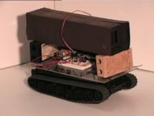 In
1988 an old Radio Shack remote control tank was converted into a test bed for
evaluating sensors for the vision contest. Using the Light Tank I developed a
differential light detector that uses two light sensors connected in a half
bridge circuit. The detector ignores changes in ambient light (like someone
turning on a video camera light) but detects edges of sudden light change (such
as the side of a light bulb or the edge of a white block). The first time this
detector was demonstrated at our robotics club the light tank
In
1988 an old Radio Shack remote control tank was converted into a test bed for
evaluating sensors for the vision contest. Using the Light Tank I developed a
differential light detector that uses two light sensors connected in a half
bridge circuit. The detector ignores changes in ambient light (like someone
turning on a video camera light) but detects edges of sudden light change (such
as the side of a light bulb or the edge of a white block). The first time this
detector was demonstrated at our robotics club the light tank 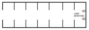 immediately
charged the president of the club and started chasing him around. He was
wearing black pants and the room had white walls. The detector can spot a
flashlight at 30 feet and a white block in a dark area at 6 feet. One of the secrets
of the detector is the light trap that reduces the stray light entering the
trap. The patricians inside the trap
capture the stray light. The trap is made out of flat black construction paper. The Atom Ant robot described below uses two
of these detectors.
immediately
charged the president of the club and started chasing him around. He was
wearing black pants and the room had white walls. The detector can spot a
flashlight at 30 feet and a white block in a dark area at 6 feet. One of the secrets
of the detector is the light trap that reduces the stray light entering the
trap. The patricians inside the trap
capture the stray light. The trap is made out of flat black construction paper. The Atom Ant robot described below uses two
of these detectors.
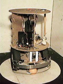
Atom Ant Robot
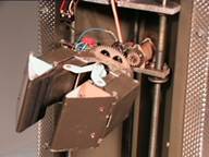
In 1988 another contest robot was designed for the block finding vision contest. It was named "Atom Ant" because it looked like it had two big eyes. Are you old enough to remember the Atom Ant cartoons with the ant wearing the big glasses? This robot was built at the last moment and used a Motorola 68HC11 single board computer. I had the computer at home to learn how to program in assembler for a project we were doing at work. The example programs were boring so I bolted the computer to some wheels and a couple of motors and it was a lot more fun to learn to program something that moves. Then just a couple of weeks before the contest I realized that this platform might be able to do the second level of the vision contest. In the second level you had to collect all four blocks and put them through the opening.
 The
robot has one drive motor and one steering motor. Two light detectors are
attached to the drive motor portion of the robot so they turn with the drive wheel.
One vertically oriented light detector with a 45 degree mirror looked for the
blocks and the horizontally oriented detector (on top) looked for the light
above the wall opening. These light detectors were developed using the Light
Tank described above. There are two other sensor inputs. One detects a block in
the block catcher and the other detects the wall when the robot enters the
opening.
The
robot has one drive motor and one steering motor. Two light detectors are
attached to the drive motor portion of the robot so they turn with the drive wheel.
One vertically oriented light detector with a 45 degree mirror looked for the
blocks and the horizontally oriented detector (on top) looked for the light
above the wall opening. These light detectors were developed using the Light
Tank described above. There are two other sensor inputs. One detects a block in
the block catcher and the other detects the wall when the robot enters the
opening.
Atom Ant was able to do the second level of the contest by locating one block at a time. Capturing it in the wire block catcher and pushing it into the opening. Navigation is simple. Point the robot to the right of the first block. The robot starts steering the detectors left looking for a block. When a block is seen turn on the drive motor. With the drive motor going steer right until the block is not seen then left until the block is seen. The robot steers its head back and forth as it advances. When the robot runs into the block it then starts looking for the light above the opening and repeats the same behavior as when it is looking for a block. When it runs into the wall it backs up and starts looking for another block. After the fourth block is inside the opening the robot backs out and stops. Well Atom Ant was able to get all four blocks in the opening a couple of times during the contest.
In 1988 and 89 a robot was built to put eye drops in our dog Susie’s eyes.
Susie’s tear glands were damaged due to an eye infection and the vet wanted us
to put drops in her eyes every couple of hours during the day. Well that is
hard to do when both 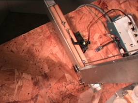 you
and your wife are away at work 9 to 10 hours a day. I thought it should be easy
to put eye drops in a dog's eyes with a robot. The first problem was Susie
hated to have the drops put in her eyes. This was solved with a dog biscuit
reward after each application.
you
and your wife are away at work 9 to 10 hours a day. I thought it should be easy
to put eye drops in a dog's eyes with a robot. The first problem was Susie
hated to have the drops put in her eyes. This was solved with a dog biscuit
reward after each application.
First a dog biscuit dispenser
was designed. The dispenser was operated with an old Radio Shack Color
Computer. The computer sounded a tone then pushes a dog biscuit out of the
dispenser just a little bit. When the dog tried to get the biscuit out of the
dispenser her nose touches a micro switch. The micro switch lets the computer
know the dog is there and ejects the dog biscuit all the way out. For 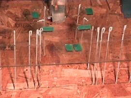 a
while the computer would sound the tone every couple of hours and we would go
over and put eye drops in and let the dog get the dog biscuit.
a
while the computer would sound the tone every couple of hours and we would go
over and put eye drops in and let the dog get the dog biscuit.
Next a frame was built to
hold the dog biscuit dispenser up high on a slanted surface. When Susie was
standing on her tip toes the surface lifted her head up at a 45 degree angle as
she reaches for the dog biscuit. After the dog became accustomed to the frame a
Plexiglas top was mounted on top of the frame that 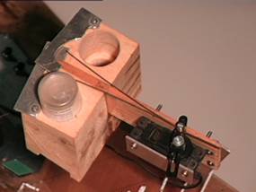 wedged
Susie’s head down when she reached for a dog biscuit. As the dog became
accustomed to the Plexiglas top pins were added to the sides to guide her head
and noise. Slowly more pins were added until the Susie had to wedge her head
into the fixture to be able to get the dog biscuit. Two small holes were
drilled in the Plexiglas cover
wedged
Susie’s head down when she reached for a dog biscuit. As the dog became
accustomed to the Plexiglas top pins were added to the sides to guide her head
and noise. Slowly more pins were added until the Susie had to wedge her head
into the fixture to be able to get the dog biscuit. Two small holes were
drilled in the Plexiglas cover 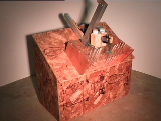 right
over the location of her eyes as she was wedged into the fixture. An eye drop dispenser was then designed
that squeezed two eye drop bottles. Finally the whole thing worked. The system
waited for two hours, sounded a tone then presents the dog biscuit part of the
way out. When Susie squeezed her head in the fixture and bites at the dog
biscuit her nose touches the micro switch. The eye drop bottles were squeezed
releasing the eye drops in the her eyes then the dog biscuit was pushed the
rest of the way out. It actually worked. The vet was real excited and was
setting up a visit for me with the vet school. Then it happened. A scientific
breakthrough! A new eye drop came on the market that lasted 12 hours. Well it
was a terrific educational experience and Susie was fat and happy while I was
working on the project.
right
over the location of her eyes as she was wedged into the fixture. An eye drop dispenser was then designed
that squeezed two eye drop bottles. Finally the whole thing worked. The system
waited for two hours, sounded a tone then presents the dog biscuit part of the
way out. When Susie squeezed her head in the fixture and bites at the dog
biscuit her nose touches the micro switch. The eye drop bottles were squeezed
releasing the eye drops in the her eyes then the dog biscuit was pushed the
rest of the way out. It actually worked. The vet was real excited and was
setting up a visit for me with the vet school. Then it happened. A scientific
breakthrough! A new eye drop came on the market that lasted 12 hours. Well it
was a terrific educational experience and Susie was fat and happy while I was
working on the project.
Parents for the Advancement of Gifted
Education
Starting in 1980 for many years members of the Triangle Amateur Robotics
Club (TAR) gave robotic presentations for the local Parents for the Advancement
of Gifted Education (PAGE) Saturday morning program in the area. This PAGE
program was developed by a group of Raleigh NC parents that wanted their gifted
children doing something better than watching TV on Saturday mornings. In the
early days we demonstrated our robots to the class and talked about robotics.
The students enjoyed the demonstrations, but it was hard to keep the gifted
student's attention when we talked. We thought the class would be better if
each student actually built a robot they could take home 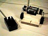 when
the class was over.
when
the class was over.
TAR Rat Robot
We developed a wire remote control robot called the TAR Rat (Rat). The Rat basically was a wooden base with two wheels, a couple of motors and a battery pack that is attached with wires to a box with two switches. The students enjoyed making the Rats and over 100 of them where built in the classes. After completing the Rats the students put their Rat's through several exercises where they simulated robotic tasks. The Rats went through several design iterations. The last version of the wire controlled TAR Rat is pictured on the right.
Organic Robot Presentation
 Because
the TAR Rats took too much out of class preparation time the Organic Robot Presentation was
developed. The Organic Robot is a simple
hands-on classroom presentation that lets students design, program and build a
simple robot in the classroom. The
presentation can be performed without tools or expensive robot kits. The Organic Robot was originally developed
for amateur robotics hobbyist to use to teach robotics to gifted elementary
school students. Since the presentation was
developed it has also been used with middle and high school students, FIRST
teams, Boy Scouts and adults.
Practically any technically oriented teacher/volunteer can learn to give
the Organic Robot presentation. The
presentation can be performed in two to three hours or used as the introduction
of an entire unit on robotics.
Because
the TAR Rats took too much out of class preparation time the Organic Robot Presentation was
developed. The Organic Robot is a simple
hands-on classroom presentation that lets students design, program and build a
simple robot in the classroom. The
presentation can be performed without tools or expensive robot kits. The Organic Robot was originally developed
for amateur robotics hobbyist to use to teach robotics to gifted elementary
school students. Since the presentation was
developed it has also been used with middle and high school students, FIRST
teams, Boy Scouts and adults.
Practically any technically oriented teacher/volunteer can learn to give
the Organic Robot presentation. The
presentation can be performed in two to three hours or used as the introduction
of an entire unit on robotics.
Only a few simple props and a black board are needed. Instead of using an expensive robot (that the whole class has to share) the presentation actually lets the students brainstorm to design the robot and brainstorm to develop a robotic programming language. After the robot is designed and the programming language is developed the students flow chart a program for the robot using their programming language. All of the design, development and programming are performed on a black board. The robot is constructed out of organic parts (the students). Then the robot executes the flow charted program.
Down load the complete Organic Robot Presentation lesson plan. A condensed version of this lesson plan was a feature article in the March, 2001 issue of Circuit Cellar magazine.
TAR Maze Contest
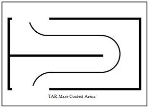 The
next TAR Club contest was a simple maze contest. The walls were a little less than a foot high
painted white. The floor was painted
white with a black line through the maze with a one foot wide path between the
walls. Again at the last moment I
designed a robot for the contest. I
added a micro switch to a TAR Rat. The
micro switch was attached to a wire that would touch the wall beside the
robot. When the wire touched the wall
the motor on the wall side turned on turning the robot away from the wall. When the wire left the wall the motor on the
side opposite the wall turned on turning the robot back toward the wall. This
The
next TAR Club contest was a simple maze contest. The walls were a little less than a foot high
painted white. The floor was painted
white with a black line through the maze with a one foot wide path between the
walls. Again at the last moment I
designed a robot for the contest. I
added a micro switch to a TAR Rat. The
micro switch was attached to a wire that would touch the wall beside the
robot. When the wire touched the wall
the motor on the wall side turned on turning the robot away from the wall. When the wire left the wall the motor on the
side opposite the wall turned on turning the robot back toward the wall. This 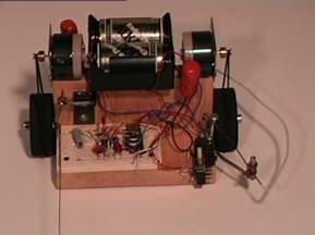 arrangement
causes the robot to wobble back and forth going along the wall. This
arrangement works great going around a wall but the robot would drive directly
into the wall in front of it at a ninety degree turn. Next I added another micro switch and a wire
that looked like a lance sticking out in front of the robot. This lance like bumper hits the wall in front
of the robot in time for it to turn. The
lance pushes the micro switch when the wall is reached. The micro switch triggers a 555 timer circuit
that is set for enough time for the robot to turn ninety degrees. The 555 timer circuit closes a relay that disables
the motor opposite the wall and powers the motor next to the wall. At the end of the set time the relay opens
returning the robot to its normal wall following wobble. This Robot (that I call Maze Rat)
dependability goes through mazes. It is
a big hit at school presentations and fellow robot experimenters can’t believe
how simple it is.
arrangement
causes the robot to wobble back and forth going along the wall. This
arrangement works great going around a wall but the robot would drive directly
into the wall in front of it at a ninety degree turn. Next I added another micro switch and a wire
that looked like a lance sticking out in front of the robot. This lance like bumper hits the wall in front
of the robot in time for it to turn. The
lance pushes the micro switch when the wall is reached. The micro switch triggers a 555 timer circuit
that is set for enough time for the robot to turn ninety degrees. The 555 timer circuit closes a relay that disables
the motor opposite the wall and powers the motor next to the wall. At the end of the set time the relay opens
returning the robot to its normal wall following wobble. This Robot (that I call Maze Rat)
dependability goes through mazes. It is
a big hit at school presentations and fellow robot experimenters can’t believe
how simple it is.
Ken’s Stomp Walker
 This
is a case where the robot came before the contest. For years I had been giving robot
presentations at schools, PAGE or Boy Scouts and always somewhere in the
presentation I would say that one day I am going to build a walking robot. I
had many drawings on napkins, notebooks and scraps of paper but nothing seemed
simple enough to attempt to make back then.
I kept thinking about those wind up toys that walked using two U shaped
feet that basically stepped over each other. I kept trying to figure out how to
make the feet so the robot could turn while standing on one leg without
stepping on itself or falling over because its center of gravity fell outside
of the U shaped foot. I did not want to
make the robot turn like old people shuffling around from one foot to the
other.
This
is a case where the robot came before the contest. For years I had been giving robot
presentations at schools, PAGE or Boy Scouts and always somewhere in the
presentation I would say that one day I am going to build a walking robot. I
had many drawings on napkins, notebooks and scraps of paper but nothing seemed
simple enough to attempt to make back then.
I kept thinking about those wind up toys that walked using two U shaped
feet that basically stepped over each other. I kept trying to figure out how to
make the feet so the robot could turn while standing on one leg without
stepping on itself or falling over because its center of gravity fell outside
of the U shaped foot. I did not want to
make the robot turn like old people shuffling around from one foot to the
other.
It was Friday night and I was giving a presentation on robot locomotion to the robotics club Monday where I knew I would again be embarrassed to say again that one day I was going to build a walking robot. I decided to go to the basement workshop and think about the walking problem again.
 I like to visualize what I am doing so I
grabbed my old Erector set and started laying out U shaped assemblies. Then eureka, discovery, light bulb flashing moment
happened. I realized how a robot could
walk and turn without stepping on its feet.
One foot could be a large elongated 0 and the other foot could be a
smaller circle that could fit/move forward and backwards inside the 0. When the robot stood up on the inner circular
foot it would lift the outer foot off the floor so the robot could freely turn
without stepping on its other foot. To
move forward it would move the outer foot forward while it stood on the inner
foot. Then the inner foot would lift lowering
the outer foot. Once the weight of the
robot was on the outer foot the inner foot would move to the front of the
elongated 0. Then the inner foot would
lower lifting the outer foot and repeat the process pushing the outer foot
forward again.
I like to visualize what I am doing so I
grabbed my old Erector set and started laying out U shaped assemblies. Then eureka, discovery, light bulb flashing moment
happened. I realized how a robot could
walk and turn without stepping on its feet.
One foot could be a large elongated 0 and the other foot could be a
smaller circle that could fit/move forward and backwards inside the 0. When the robot stood up on the inner circular
foot it would lift the outer foot off the floor so the robot could freely turn
without stepping on its other foot. To
move forward it would move the outer foot forward while it stood on the inner
foot. Then the inner foot would lift lowering
the outer foot. Once the weight of the
robot was on the outer foot the inner foot would move to the front of the
elongated 0. Then the inner foot would
lower lifting the outer foot and repeat the process pushing the outer foot
forward again.
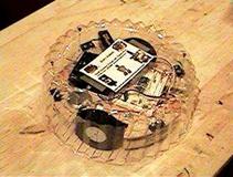
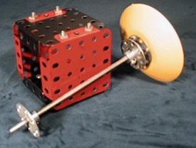 I
quickly assembled the robot out of the Erector set parts and used double sided
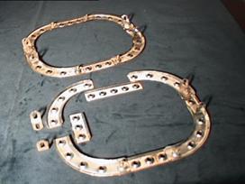
tape to attach three RC servos, a battery and RC receiver. The yellow inner foot is an Erector
Radar/Communications dish. The outer 0
is made up of the larger Erector quarter circle pieces with straight pieces to
elongate and widen the 0. Most of the
heavy items (batteries, servos and electronics) were connected to a red cube
made from square Erector pieces.
I
quickly assembled the robot out of the Erector set parts and used double sided
tape to attach three RC servos, a battery and RC receiver. The yellow inner foot is an Erector
Radar/Communications dish. The outer 0
is made up of the larger Erector quarter circle pieces with straight pieces to
elongate and widen the 0. Most of the
heavy items (batteries, servos and electronics) were connected to a red cube
made from square Erector pieces.
 The
red cube is attached to the outer foot by two Erector axels that go through the
cube allowing the cube to slide forward and backwards inside of the outer
foot. One forward backwards servo is
attached between the cube and the outer foot (on the fourth photograph it is on
the right/back side of the red cube).
The
red cube is attached to the outer foot by two Erector axels that go through the
cube allowing the cube to slide forward and backwards inside of the outer
foot. One forward backwards servo is
attached between the cube and the outer foot (on the fourth photograph it is on
the right/back side of the red cube).
The inner foot is mounted on an axel that goes vertically through the center of the red cube. The outer foot lift servo/lower foot push down servo is seen in the fifth photograph attached below the red cube. A circular servo arm is seen that has been modified to be a cam that pushes down on an Erector pulley. The back unmodified side of the servo arm cam rests against the red cube so all of the robot’s weight is on the cam instead of the servo. In the photograph the cam is in the inner foot down/outer foot up position. Notice that the inner foot is below the outer foot.
 The
turn servo is attached to the front side of the red cube. The servo’s arm is connects to an Erector hub
attached to the top of the vertical inner foot.
This hub is turned by the servo which turns the inner foot which turns
the robot when the robot is supported by the inner foot. Between the hub and the top of the red cube
is a spring that lifts up the inner foot when the cam rises.
The
turn servo is attached to the front side of the red cube. The servo’s arm is connects to an Erector hub
attached to the top of the vertical inner foot.
This hub is turned by the servo which turns the inner foot which turns
the robot when the robot is supported by the inner foot. Between the hub and the top of the red cube
is a spring that lifts up the inner foot when the cam rises.
I connected the servos with the lift servo the RC plane throttle position, the front back on the elevator position and the turn on the aileron position. That seemed to make since at the time. I was definitely not coordinated enough to easily make the robot walk. Shortly after getting it going one of the servos failed and I had to dismantle the robot to replace it. When it was reassembled the servo connections were accidently changed putting the lift and front back servos on the elevator and aileron positions. To my amazement with this new servo arrangement all I had to do was move the elevator/aileron control stick in clockwise circles to make the robot walk forward and counter clockwise to make it walk backwards.
At the club meeting that Monday evening the robot locomotion presentation was well received. However at the end of the presentation where in the past I would have to say “One of these days I am going to build a walking robot” I pulled out my new walker and said one of these days I will make the Stomp Walker a robot.
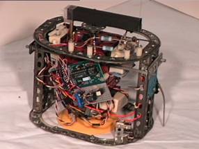
 4
Unique design features
4
Unique design features 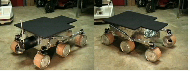 Triangle
Amateur Robotics (TAR) Club members built a mock up of the Mars rover in the
Ken's Robots workshop.
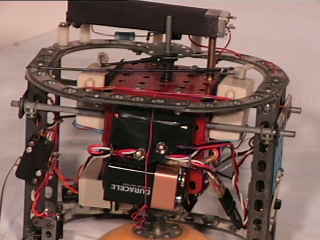
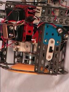
Triangle
Amateur Robotics (TAR) Club members built a mock up of the Mars rover in the
Ken's Robots workshop.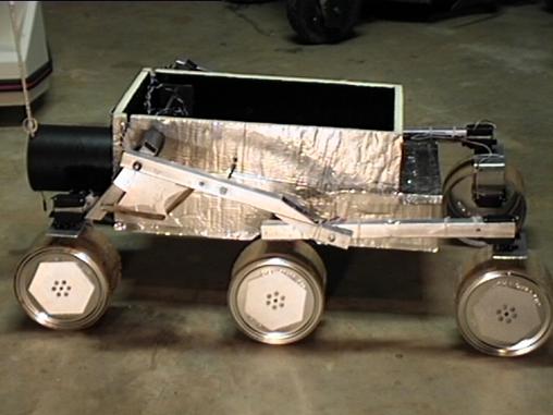 The
rover has five modes of operation: stop, forward, backwards, rotate clockwise
and rotate counter clockwise. The BASIC Stamp 2 monitors two RC channels from
the receiver and gives the proper signals to each of the 10 servos based on the
commanded mode of operation. The rover’s speed varies with control stick
deflection.
The
rover has five modes of operation: stop, forward, backwards, rotate clockwise
and rotate counter clockwise. The BASIC Stamp 2 monitors two RC channels from
the receiver and gives the proper signals to each of the 10 servos based on the
commanded mode of operation. The rover’s speed varies with control stick
deflection.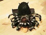
 2005
was the 6th year I taught a robotics class for the
2005
was the 6th year I taught a robotics class for the 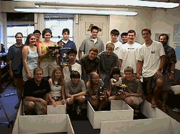
 building
a robot of their own. During this introduction period each student builds a
copy of the robot that I designed for the course. With a combination of
instruction and learning by doing the students learn how to read mechanical
drawings and schematics, use
building
a robot of their own. During this introduction period each student builds a
copy of the robot that I designed for the course. With a combination of
instruction and learning by doing the students learn how to read mechanical
drawings and schematics, use 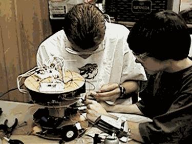 simple
tools, and do mechanical layout, sawing, drilling, soldering, wiring and
programming. During the last week and a half of the course the students are
divided into four teams and each team builds a fire fighting robot using the
box of identical materials given to each team. The
simple
tools, and do mechanical layout, sawing, drilling, soldering, wiring and
programming. During the last week and a half of the course the students are
divided into four teams and each team builds a fire fighting robot using the
box of identical materials given to each team. The 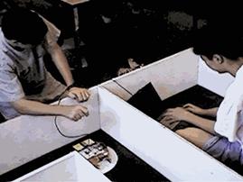 classes
have been a great success and everyone had a great time. Thanks for the help of
Bob Hamlin who helps teach the course and Nancy Womack (98 class), Kevin
McGowan (99 class), Lori Webber (2000 class), Dennis Chin (2001 class), Dana
Scott (2003 class) and William Cox (2005 class) college student teaching
assistants.
classes
have been a great success and everyone had a great time. Thanks for the help of
Bob Hamlin who helps teach the course and Nancy Womack (98 class), Kevin
McGowan (99 class), Lori Webber (2000 class), Dennis Chin (2001 class), Dana
Scott (2003 class) and William Cox (2005 class) college student teaching
assistants. 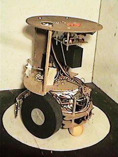
 2000/01
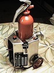
 Jake
Mendelson started the Fire Fighting contest and mentioned to me that the tenth
year would be his last year.
Jake
Mendelson started the Fire Fighting contest and mentioned to me that the tenth
year would be his last year.
 don’t
have bumpers or the bumpers are not designed well and break.
don’t
have bumpers or the bumpers are not designed well and break.
 I
had a medical close call a while back and while recuperating I saw the movie
Bucket List.
I
had a medical close call a while back and while recuperating I saw the movie
Bucket List.